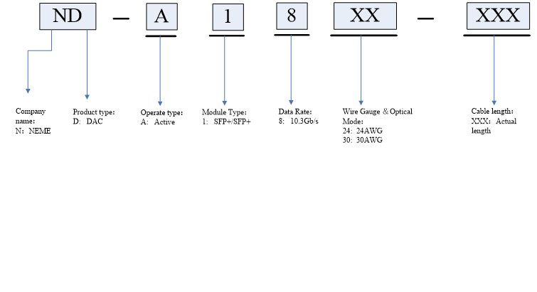
10G SFP+Direct Attach Active Copper Cables
1. Applications
- 10G Ethernet
- InfiniBand, Fiber Channel 4G/8G/10G
- Sonet Multiplatform support
- High Performance Computing Clusters
- High End Servers
- Metro Network Switch/Cross Connect
2. Features
- Active Copper (Equipped with chipset as signal repeater) (Cable Length: 0.5~15m)
- Support for multi-gigabit data rates up to 10.5Gbps
- Data rates backward compatible to 1Gbps
- Hot-pluggable SFP 20PIN footprint
- I/O Connector designed for high speed differential signal applications
- Improved Pluggable Form Factor(IPF) compliant for enhanced EMI/EMC performance
- Compatible with industry standard SFP cages +Switches
- EEPROM signature can be customized.
- Low Power Consumption < 0.5W
- Temperature Range: 0~ 70 °C
- RoHS-6 Compliant
| Cisco Genuine | SFP-H10GB-CU50CM | Vendor Name | 10GLINK-Fiber.COM |
| Connector Type | SFP+ to SFP+ | Max Data Rate | 10Gbps |
| Minimum Bend Radius | 20mm | Wire AWG | 30AWG |
| Cable Length | 0.5m(1.64ft) | Jacket Material | PVC(OFNR) |
| Temperature | 0 to 70°C (32 to 158°F) | Protocols | 1x InfiniBand QDR, DDR, SDR, 10G Gigabit Ethernet, Fibre Channel |
3. Description
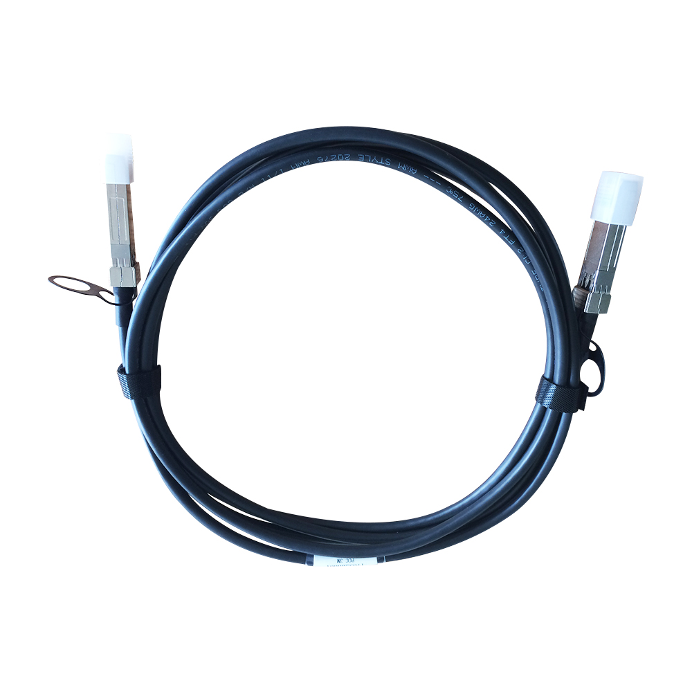
10G-Link Fiber high speed SFP+ DirectAttach Cable (DAC) provides high performance in 10 Gigabit Ethernet (10GbE) network applications, using an enhanced SFP+ connector to send 10Gbps data through one paired transmitters and receivers over a thin twinax cable. They are compliant with electrical standards SFF-8431, SFF-8083 and mechanical standard SFF-8432, EEPROM standard SFF-8472.
4. standard
- Compliant with electrical standards SFF-8431, SFF-8083
- Compliant with mechanical standard SFF-8432
- Compliant with EEPROM standard SFF-8472
- RoHS Compliant
5. Performance Specifications
5.1. Absolute Maximum Ratings
These values represent the damage threshold of the module. Stress in excess of any of the individual Absolute Maximum Ratings can cause immediate catastrophic damage to the module even if all other parameters are within Recommended Operating Conditions.
Table.1 Absolute maximum ratings
|
Parameter |
Symbol |
Min |
Max |
Unit |
|
Maximum Supply Voltage |
Vcc |
0 |
3.6 |
V |
|
Storage Temperature |
Ts |
-40 |
85 |
°C |
|
Relative Humidity |
RH |
5 |
95 |
% |
5.2. Recommended Operating Conditions
Table.2 Recommended Operating Conditions
|
Parameter |
Symbol |
Min |
Typical |
Max |
Unit |
|
Operating Case Temperature |
Standard Tc |
0 |
25 |
70 |
°C |
|
Storage Temperature |
Ts |
-40 |
|
85 |
°C |
|
Power Supply Voltage |
Vcc |
3.13 |
3.30 |
3.47 |
V |
|
Power Dissipation |
PD |
|
|
0.5 |
W |
|
Relative Humidity |
RH |
5 |
|
95 |
% |
|
Data Rate |
|
|
10.5 |
|
Gbps |
5.3.Product Specification
Table.3 Product Specification
|
Test Type |
Test Item |
Target |
Reference |
|
Electrical Characteristics |
Differential Mode RL(SDDII) | 0.01<f<4.1 ; < -12+2*SQRT(f )4. 1<f<11. 1 ; <-6.3+13*log10(f/5.5)Where f is in GHzMeasurements units: dB | SFF 8431 |
| Common mode return loss (SCCII) | 0.01<f<2.5 ; <-7+1.6(f )2.5<f<11.1 ; <-3Where f is in GHzMeasurements units: dB | SFF 8431 | |
| NEXT | <-26dB from 1MHz to 11GHz | / | |
| Cable assembly Impedence | 100+/ -100hmRise time of 30 ps (20 %- 80 %) | (20%~80 %) | |
| Insertion Loss Deviation | -1dB≤ILD≤1dB300KHz≤f≤6GHz | / | |
|
EnvironmentalCharacteristics
|
Operating Temperature | -40~85°C | Cable operating temp.range |
| Thermal Shock | Electrical performance meet the specification requirement | EIA-364-32D. Method A. TC-1. -55 10 85C,100 cycles, 15 min, dwells | |
| Cyclic Temp. & Humidity | Electrical performance meet the specification requirement | EIA-364-31 Method III,Test Cond A | |
| Salt spray | 48 hours salt spraying after shell corrosive area less than 5% | EIA-364-26 | |
| Temperature Life | Performance meets the specification requirement | EIA-364-17B w/ RH, Damp heat 85C at 85% RH for 500 hours | |
|
MechanicalCharacteristics
|
MechanicaIVibration | Performance meets the specification requirement | EIA-364-28E.11 TC-VII, Test Cond. D 15minutes in X,Y,Z axis. |
| Cable Plug Retention in Cage | 90N Min. | No functional damage to cable plug below 90N. Per SFF-8432 Rev 5.0 | |
| Cable Retention in Plug | 90N Min. | EIA-455-6B | |
| Mechanical Shock | Performance meets the specification requirement | Clamp and Shock per EIA-364-27B, TC-G, 3times in 6directions, 100g, 6ms | |
| Cable plug Insertion | 18N(Max.) | SFF-8432 Rev 5.0 | |
| Cable plug extraction | 12.5N(Max.) | SFF-8432 Rev 5.0 | |
| Durability | 50 Time. No evidence of physical damage | EIA-364-09; performplug&unplug cycles Plug and Receptacle mate rate: 250times/hour |
4.6. Pin Definitions
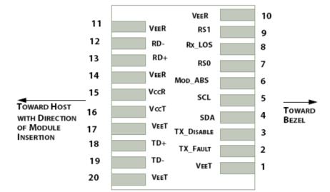

Table.8Pin Definitions
|
PIN |
Symbol |
Description |
Remarks |
|
1 |
VEET |
Transmitter ground (common with receiver ground) |
Circuit ground is isolatedfrom chassis ground |
|
2 |
Tx_Fault |
Transmitter Fault. Not supported |
|
|
3 |
Tx_Disable |
Transmitter Disable. Laseroutput disable on high or open |
Disabled: TDIS>2V or open Enabled: TDIS<0.8V |
|
4 |
SDA |
2-wire Serial Interface Data Line |
Should Be pulled up with4.7k – 10kohm on hostboard to a voltage between2V and 3.6V |
|
5 |
SCL |
2-wire Serial Interface Clock Line |
|
|
6 |
MOD_ABS |
Module Absent. Grounded within the module. |
|
|
7 |
RS0 |
No connection required |
|
|
8 |
RX_LOS |
Loss of Signal indication. Logic 0 indicates normal operation |
LOS is open collector output |
|
9 |
RS1 |
No connection required |
|
|
10 |
VEER |
Receiver ground (common with transmitter ground) |
Circuit ground is isolatedfrom chassis ground |
|
11 |
VEER |
Receiver ground (common with transmitter ground) |
|
|
12 |
RD– |
Receiver Inverted DATA out. AC coupled |
|
|
13 |
RD+ |
Receiver Non-inverted DATA out. AC coupled |
|
|
14 |
VEER |
Receiver ground (common with transmitter ground) |
Circuit ground is isolatedfrom chassis ground |
|
15 |
VCCR |
Receiver power supply |
|
|
16 |
VCCT |
Transmitter power supply |
|
|
17 |
VEET |
Transmitter ground (common with receiver ground) |
Circuit ground is isolatedfrom chassis ground |
|
18 |
TD+ |
Transmitter Non-Inverted DATA in. AC coupled |
|
|
19 |
TD– |
Transmitter Inverted DATA in. AC coupled |
|
|
20 |
VEET |
Transmitter ground (common with receiver ground) |
Circuit ground is isolatedfrom chassis ground |
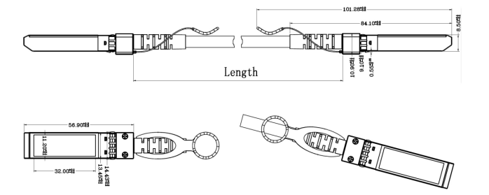
5.9. Mechanical Dimensions
6. Aplication Cautions
6.1. ESD
This transceiver is specified as ESD threshold 1kV for high speed pins and 2kV for all other electrical input pins, tested per MIL-STD-883, Method 3015.4 /JESD22-A114-A (HBM). However, normal ESD precautions are still required during the handling of this module. This transceiver is shipped in ESD protective packaging. It should be removed from the packaging and handled only in an ESD protected environment.
6.2. LASER SAFTY
This is a Class 1 Laser Product according to IEC 60825-1:1993:+A1:1997+A2:2001. This product complies with 21 CFR 1040.10 and 1040.11 except for deviations pursuant to Laser Notice No. 50, dated (July 26, 2001)
6.3. Important Notice
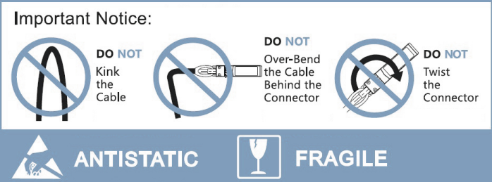
Note:
1)Copper type maximum length recommended at 15 meters;
2)Various cable lengths available for all types;
3)Latch/tab available”on top”or”bottom”position.