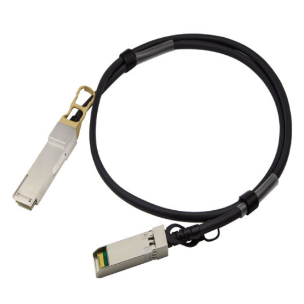
40G QSFP+ to QSFP+ Passive Direct Copper Cables
1. Applications
- 10 Gigabit Ethernet 4
- 0 Gigabit Ethernet
- InfiniBand4x SDR, DDR, QDR
- 2, 4, 8, 10 Gigabit Fiber Channel
- Fiber Channel over EthernetSAS,Servers,Hubs,Switches,Routers
- QSFP+ DAC, 40G DAC, DAC Cable
2.Features
- QSFP+ conforms to the Small Form Factor SFF-8436
- 4-Channel Full-Duplex Passive Copper Cable Transceiver
- Support for multi-gigabit data rates :1 Gb/s – 10 Gb/s (per channel)
- Maximum aggregate data rate: 40 Gb/s (4 x 10Gb/s)
- Copper link length up to 5m (passive limiting)
- High-Density QSFP 38-PIN Connector
- Power Supply :+3.3V
- Low power consumption: 0.02 W (typ.)
- I2C based two-wire serial interface for EEPROM signature which can be customized
- Temperature Range: 0~ 70 °C
3. Description
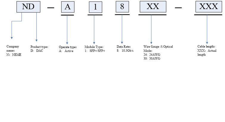
40G QSFP+ Passive Copper Cables(ND-P4CXX-XXX) are high performance,cost effective I/O solutions for 40G LAN, HPC and SAN applications. The QSFP+ passive copper cables are compliant with SFF-8436, QSFP+ MSA and IEEE P802.3ba 40GBASE-CR4. It is offer a low power consumption,short reach intercon- nect applications. The cable each lane is capable of transmitting data at rates up to 10Gb/s, providing an aggregated rate of 40Gb/s.
40G QSFP+ Passive Copper Cbales are customized for an ultra-high performance, cost effective cable solution in 40-Gigabit speed applications including switched fabric I/O, switches, routers, data storage arrays, and high performance computer (HPC) clusters.
4. standard
- 10 Gigabit Ethernet 4
- 0 Gigabit Ethernet
- InfiniBand4x SDR, DDR, QDR
- 2, 4, 8, 10 Gigabit Fiber Channel
- Fiber Channel over Ethernet SAS,Servers,Hubs,Switches,Routers
- SFP+ DAC, 40G DAC, DAC Cable
5. Performance Specifications
5.1. Absolute Maximum Ratings
These values represent the damage threshold of the module. Stress in excess of any of the individual Absolute Maximum Ratings can cause immediate catastrophic damage to the module even if all other parameters are within Recommended Operating Conditions.
Table.1 Absolute maximum ratings
|
Parameter |
Symbol |
Min |
Max |
Unit |
|
Maximum Supply Voltage |
Vcc |
0 |
3.6 |
V |
|
Storage Temperature |
Ts |
-40 |
85 |
°C |
|
Relative Humidity |
RH |
5 |
95 |
% |
5.2. Recommended Operating Conditions
Table.2 Recommended Operating Conditions
|
Parameter |
Symbol |
Min |
Typical |
Max |
Unit |
|
Operating Case Temperature |
Standard Tc |
0 |
25 |
70 |
°C |
|
Storage Temperature |
Ts |
0 |
70 |
°C |
|
|
Relative Humidity |
RH |
5 |
95 |
% |
|
|
Data Rate |
40 |
Gbps |
|||
|
Power Dissipation |
PD |
0.02 |
W |
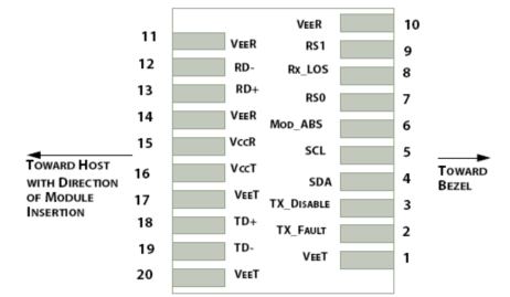
5.3. Pin Definitions
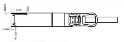
5.4. Mechanical Dimensions
6. Aplication Cautions
6.1. ESD
This transceiver is specified as ESD threshold 1kV for high speed pins and 2kV for all other electrical input pins, tested per MIL-STD-883, Method 3015.4 /JESD22-A114-A (HBM). However, normal ESD precautions are still required during the handling of this module. This transceiver is shipped in ESD protective packaging. It should be removed from the packaging and handled only in an ESD protected environment.
6.2. LASER SAFTY
This is a Class 1 Laser Product according to IEC 60825-1:1993:+A1:1997+A2:2001. This product complies with 21 CFR 1040.10 and 1040.11 except for deviations pursuant to Laser Notice No. 50, dated (July 26, 2001)
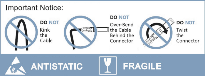
6.3. Important Notice
Note:
1)Copper type maximum length recommended at 15 meters;
2)Various cable lengths available for all types;
3)Latch/tab available”on top”or”bottom”position.
